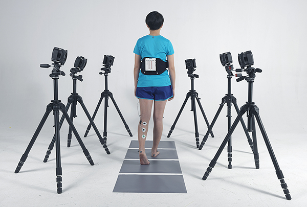
Optical motion capture systems operate on the principle of infrared optics and, compared to inertial motion capture systems, GPS positioning, and other location methods, feature high precision, low latency, strong real-time capabilities, and are mainly used in indoor settings. The system setup process can be divided into three parts: system construction, data collection and transmission, and data recognition and processing.
1 System Construction
1.1 Site Construction
An optical motion capture system is composed of infrared optical cameras, motion capture software, reflective markers, POE switches, cables, calibration frames, and tripod-based camera mounting equipment.
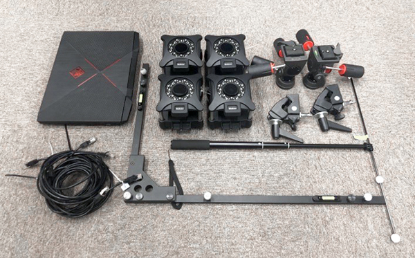
First, infrared optical cameras are arranged around the site using tripods, clamps, and other camera mounting devices to ensure that the camera field of view covers the capture area. Then, all the cameras are connected to the POE switch using Ethernet cables. The cameras are powered and transmit data through the POE switch and are connected to the motion capture software on a computer. After the software is started, the motion capture cameras are connected in real-time mode on the interface.
1.2 Site Calibration
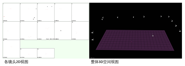
After the system's hardware and software are successfully assembled and interconnected, the next step is the calibration of the site, which includes L-type and T-type calibrations. Their purpose is to establish an XYZ coordinate system for the motion capture area, calculate the position and orientation of each camera within the coordinate system, and only after calibration can the 3D coordinate data of each marker point in the site be accurately obtained.
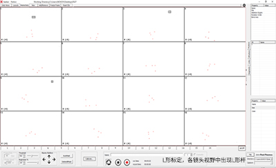
L-shape calibration is carried out by placing an L-shaped calibration rod in the center of the field and setting up the corresponding parameters in the software. This process has two purposes: first, to establish a unified coordinate system by locating four points on the L-rod, which allows the system to distinguish its long axis from its short axis, thus defining the orientation and origin of the world coordinate axes. Second, this process provides an initial set of parameters for the cameras that see the L-rod, serving as a starting point for further parameter optimization.
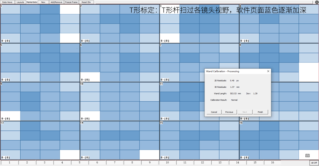
T-calibration is designed to provide each camera with sufficient data for parameter iteration and optimization based on initial values. During this process, the software is in T-calibration mode, and the operator swings a T-bar within the area, allowing the cameras to capture a large amount of data in real-time.
2 Data Collection and Transmission
2.1 Data Collection

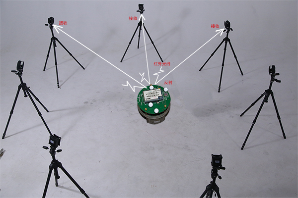
After calibration, the spatial data of the object to be captured can be acquired. Reflective markers (small silver-gray spheres coated with a special reflective substance) are placed on the surface of the person or object to be located. The motion capture cameras emit infrared light from their LEDs, which is then reflected back by the reflective markers. When multiple optical cameras "see" a marker simultaneously, that marker's 3D position in space is determined.
2.2 Data Transmission
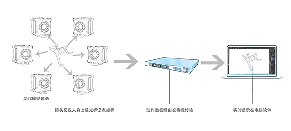
The position information of the reflective markers captured by the cameras needs to be transmitted to a computer in real-time for data processing and use. In an optical motion capture system, all cameras are connected to a switch via Ethernet cables. After the cameras capture the spatial position information of the reflective markers, this information is transmitted to the switch through the Ethernet cables and then sent from the switch to the connected computer, where it is received in real-time by the motion capture software.
3 Data Recognition and Processing
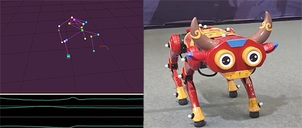
After the software obtains the 3D spatial positions of multiple reflective markers, the next step is object recognition. When multiple reflective markers are attached to the same object's surface, the distances between these specific points are constant. Therefore, the points on the same object are named, and the relationships between points are represented by connecting them with lines. This set of point names and line information is recorded in the software as a Markerset. When an object with this Markerset information appears in the field, it is recognized by the system as an independent object.
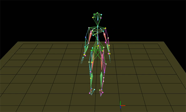
Some human motion capture processes require a large number of markers to collect data. There are specific marker models available for use. Reflective markers are attached to predetermined positions on the human body, and the markers are then recognized, connected, and bound to a skeleton within the software.
Once the system can identify the object to be captured in real-time, a complete optical motion capture system is established. Next, motion capture can be directly performed, and the captured model data can be adjusted and corrected in real-time within the software. Depending on the requirements of different fields, optical motion capture systems can also be synchronized with force plates and other devices to capture both movement and force data or be connected to 3D software for virtual character creation.