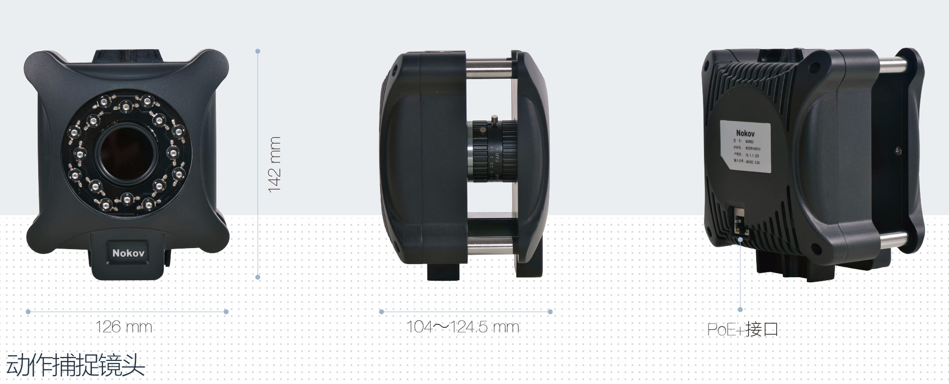
An optical motion capture system comprises infrared motion capture cameras, motion capture software, reflective markers, a POE switch, and various accessories such as calibration frames and camera mounting devices. Essentially, it is a positioning system that calculates and analyzes to provide multiple kinematic data, including velocity and acceleration.

The optical motion capture camera is the core of the motion capture system, and the camera's resolution and field of view determine the motion capture effects and precision of the entire system.
Optical motion capture technology is based on infrared light, utilizing multiple cameras to observe and locate specific markers to determine their spatial positions. The cameras' LED lights emit infrared light of a specific wavelength, which illuminates the reflective markers on the captured subject. The reflective material on the markers' surface reflects the infrared light back to the cameras. The reflected light is processed, and the FPGA captures the images and processes the algorithms, obtaining the two-dimensional coordinates of the reflective markers in the camera's view. A motion capture system usually includes multiple cameras, and by calibrating each camera, their precise positions are determined to obtain 3D coordinates.

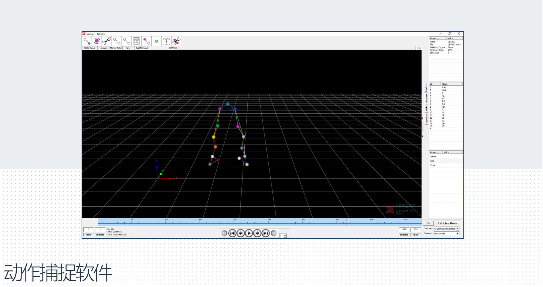
The motion capture operation and analysis processing software Seeker can combine the two-dimensional coordinates obtained from multiple cameras in the system and the spatial position information of each camera. Through calculations on the software side, it provides data such as six degrees of freedom (6DoF), yaw angle, roll angle, pitch angle, Euler angles, etc.
At the same time, it is capable of real-time processing, supporting the completion of system calibration, correction, data collection, and export. The acquired data can be transmitted via VRPN, or broadcast through an SDK (C++ language) port to communicate with software like ROS, Labview, Matlab (including Simulink) for secondary development.

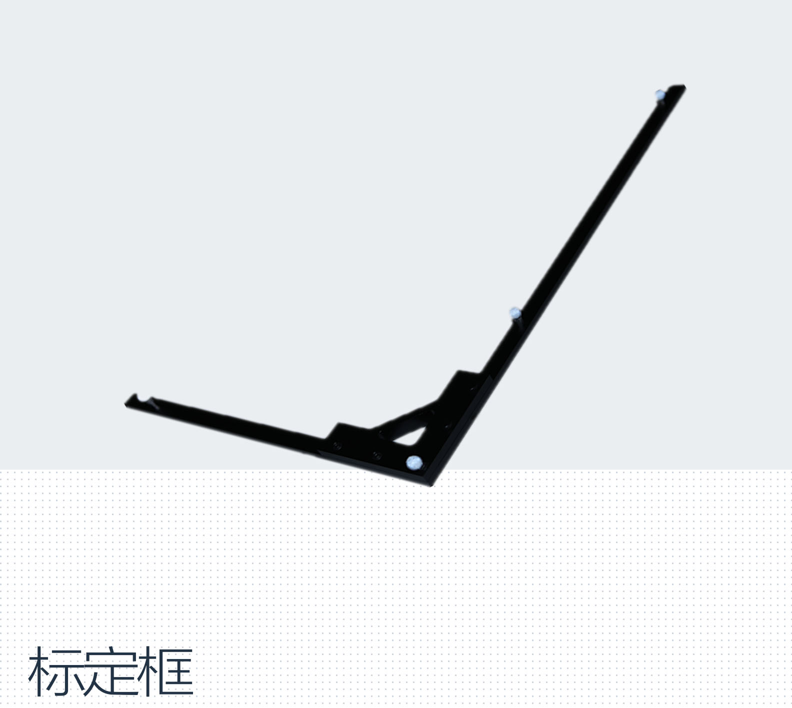
A calibration frame is a calibration tool used during the calibration of an optical motion capture system. After the motion capture software calculates the precise spatial position and angle of the cameras, it establishes a 3D spatial coordinate system (XYZ axes). Using the L-type calibration tool, which is the calibration frame, the directions and origin of the X, Y, and Z axes in space are determined, preparing for accurate motion capture.

In optical motion capture systems, the targeted object is affixed with markers that reflect infrared light. The reflective material on the surface of these markers reflects the infrared light, which is then received by sensor arrays on multiple camera lenses to capture relevant data.![]()

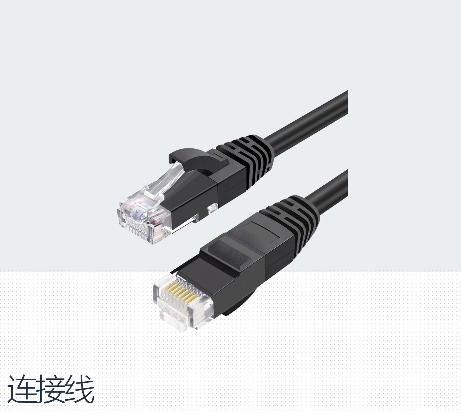
refers to standard Ethernet cables that use Power over Ethernet technology, allowing for both data transmission and power supply through a single cable.

In data transmission, a POE switch receives 3D positional data transferred from optical motion capture cameras via Ethernet cables and transmits it to a computer. This enables the motion capture software to perform further algorithmic processing of the data to obtain 3D coordinates, acceleration, and other motion data. The POE switch can also power the cameras via Ethernet cables.

Includes tripods, pan-tilt heads, and clamps. Tripods can be used in situations with limited mounting conditions or in more open spaces, while clamps and pan-tilt heads are also utilized to secure the camera in a variety of environmental conditions.

The Mars4H UW lens surface has undergone special anti-corrosion and anti-rust treatment, and the system operates on infrared optical principles, unaffected by external magnetic field changes.
