Abstract
This case study presents the use of motion capture in research on mechanical logic based on 3D-printed chiral structures. Professor Nan Yang's team at Shantou University used NOKOV motion capture system to obtain high-precision position data from the vertical panels of the chiral structures. These measurements supported the analysis of structural mechanical behavior and the validation of stiffness, helping the team verify a mechanical logic computing approach based on chiral structures.
Article Overview
A research team at Shantou University proposed a method for implementing mechanical logic with 3D-printed chiral structures. Through interactions among multiple chiral units, the system achieved continuously tuneable stiffness and mechanical logic computation.
The researchers built a buffer, a NOT gate, and six additional fundamental logic gates. They further demonstrated combinational logic through a half-adder, confirming the feasibility of the mechanical computing approach.
During the experiments, NOKOV motion capture system tracked reflective markers on the vertical panels of the chiral structures and calculated changes in the twist angle during compression.
The motion capture measurements were used to analyze the mechanical behavior of the chiral structures and to support stiffness validation, providing position data for the experimental analysis.
This case demonstrates how optical motion capture can support mechanical testing of metamaterials and structural deformation measurement.
Professor Nan Yang's research team at Shantou University recently published the paper '3D-printed chiral-based systems with reprogrammable stiffness for mechanical logics via inter-unit interactions' in Virtual and Physical Prototyping. The study introduced a mechanical logic computing method based on chiral structures. Continuously tuneable stiffness was achieved through interactions among multiple chiral units, and the same principle was used to build fundamental logic gates and a combinational logic system such as a half-adder.
In the study, NOKOV motion capture system measured changes in the twist angle of the chiral structures during compression, supporting the quantitative characterization of their mechanical properties.
Citation
Yang, N., Luo, J., Lan, Y., Wei, H., and Padovani, D. (2026). 3D-printed chiral-based systems with reprogrammable stiffness for mechanical logics via inter-unit interactions. Virtual and Physical Prototyping, 21(1), e2650248. https://doi.org/10.1080/17452759.2026.2650248
Research Background
Mechanical computing is attracting renewed interest because of its potential to complement electronic computation. The coupled compression-twist response of chiral metamaterials under external loading is well suited to mechanical logic. However, previously reported examples of reprogrammable mechanical behavior had not been applied directly to mechanical computation. Chiral acoustic devices could switch only between AND and OR gates through stretching, and research on complex logic functions created through interactions among multiple chiral structures remained limited.
Contributions of This Study
The research team proposed a method based on chiral structures with suitable compression-twist behavior and continuously tuneable stiffness. Digital information is processed through interactions among the structures. Tailor-made chiral structures act as switches for electrical signals, enabling electronics-free logic calculations. The team created a buffer unit and a NOT gate, which served as the essential building blocks for the other six fundamental logic gates: AND, OR, XOR, NAND, NOR, and XNOR. The computing capability was then extended to a combinational logic system through an experimentally implemented and tested half-adder. Because the method is mechanical in nature, it may offer advantages in harsh environments and enable direct interaction with the surroundings, complementing conventional electronic computation.
Methods
Structural Design
As shown in the upper part of Figure 1a, each sub-unit consists of a round top plate and a square bottom plate connected by four struts with circular cross-sections. Two sub-units are combined into a two-layer chiral unit that shares an intermediate plate, as shown in the lower part of Figure 1a. The total unit height is 52 mm. The distance between the centers of two opposite struts on the top plate is fixed at d = 20 mm, while the anchoring distance on the intermediate plate, d_m, is set to 10, 20, or 40 mm. Four vertical panels are arranged on the intermediate plate of each unit.
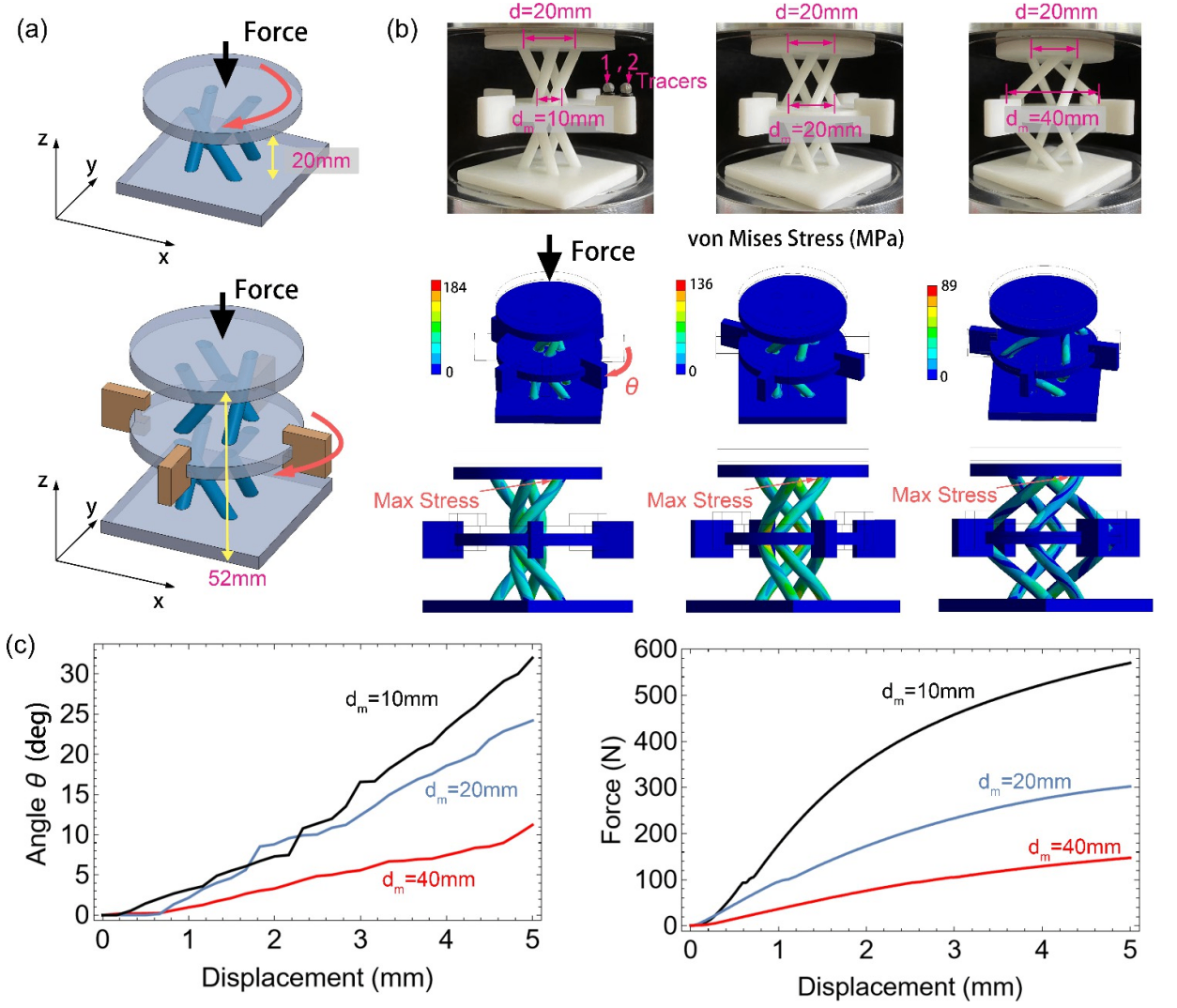
Figure 1. Chiral structure designs and their mechanical behaviour. (a) Sub-unit (top), and single-unit (bottom), (b) Photographs of prototypes with different anchoring locations of the struts (dm = 10, 20, and 40 mm), visualisation of the corresponding von Mises stress obtained with finite element analyses, and definition of the twist angle u. (c) Twisting angle/vertical displacement trends and force/vertical displacement curves (experimental results).
Mechanical Properties
NOKOV motion capture system tracked two reflective spherical tracers, each 3 mm in diameter, fixed to the upper edges of the vertical panels. Their motion was used to calculate the twist angle of the rotating intermediate plate. The motion capture system operated in coordination with a CMT5105 universal testing machine, which compressed the top surface of the chiral structure and imposed a vertical displacement of Delta L = 5 mm. Three specimens with different geometries were tested. Compressive force and displacement were recorded, and structural stiffness was obtained by fitting the elastic region of the force-displacement curves.
Results and Discussion
Mechanical Behavior of a Single Unit
When the unit was compressed, its struts bent, as shown in Figure 1b. The maximum von Mises stress occurred at the interface between the struts and the top plate, and a smaller d_m produced a higher stress. The experimental trends in Figure 1c show that, for the same vertical displacement, increasing d_m reduced both the twist angle and the required actuation force. The twist-angle/displacement curves were approximately linear, while the force/displacement curves were nearly parabolic. A value of d_m = 20 mm provided a useful compromise: it helped preserve unit integrity during repeated operation while still producing a substantial twist angle at a given vertical displacement.

Table 1. Simulated and measured stiffness values k of three single units with different distances dm between struts anchored on the intermediate plate (see Figure 1).
Interaction Between Two Units
The interaction between the two units shown in Figure 2 enabled reprogrammable stiffness. The left unit was fixed, while the right unit could slide. Changing the overlap distance s between the vertical panels of the two contacting units changed the stiffness of the assembly. The measurements reported in Figure 2b correspond to the four configurations shown in Figure 2c.
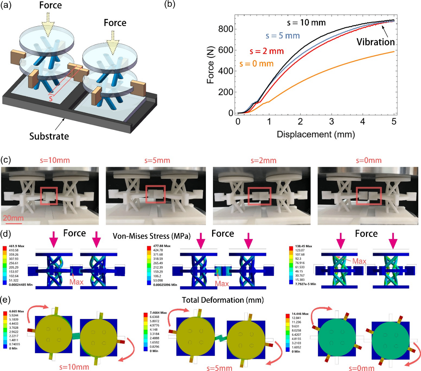
Figure 2. Reprogrammable stiffness of the system comprising two units. (a) Visualisation of two units and their substrate, with the indication of the overlap distance s. (b) Measured force-displacement curves with s = 10, 5, 2, and 0mm, and dm = 20 mm, and (c) Corresponding photographs of the two-unit assemblies. Resulting (d) von Mises stress in the two units and (e) deformation under a 5 mm compression.
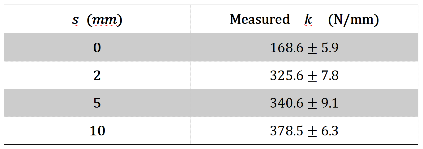
Table 2. Measured stiffness values k of two interacting units with overlaps s = 0, 2, 5 and 10mm with a distance dm = 20mm between the struts (see Figure 2).
Interaction Among Five Units
Combining more units increased the number of available reprogrammable stiffness values. As shown in Figure 3a, the team connected five units with a dedicated substrate. The central unit was fixed in a tight groove and interacted with four neighboring units. Each neighboring unit could slide in only one direction within its groove, allowing different overlap distances s to be established.
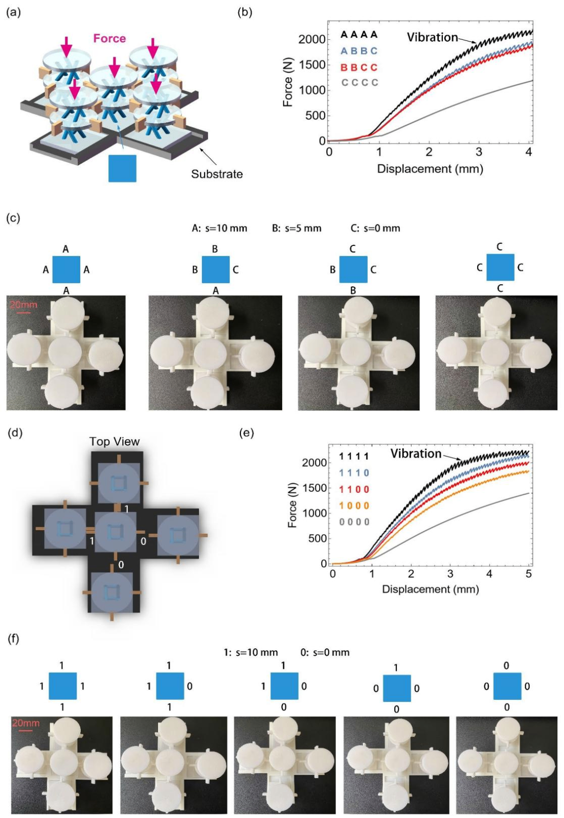
Figure 3. Achieving reprogrammable stiffness by combining five units with dm = 20 mm. (a) The central (fixed) unit, schematised with a blue square, interacts with four (sliding) neighbouring units. (b) Measured force-displacement curves based on different adjustments (patterns) of the neighbouring units. (c) Experimental photographs of four patterns of interest (AAAA, ABBC, BBCC and CCCC), where the letters A, B, and C designate the overlap distance of the vertical panels between units equal to s = 10, 5 and 0 mm, respectively. (d) Top view of the central unit interacting with four neighbours with a binarized overlap distance between units using s = 10 mm indicated as ‘1’ and s = 0 mm marked as ‘0’, (e) corresponding measured force-displacement curves and (f) photographs of the achievable patterns.
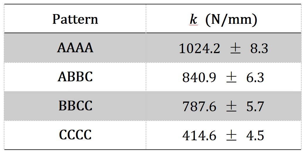
Table 3. Measured stiffness values k of the system comprising five units with patterns achieved by combining overlapdistances s = 10, 5 and 0 mm.
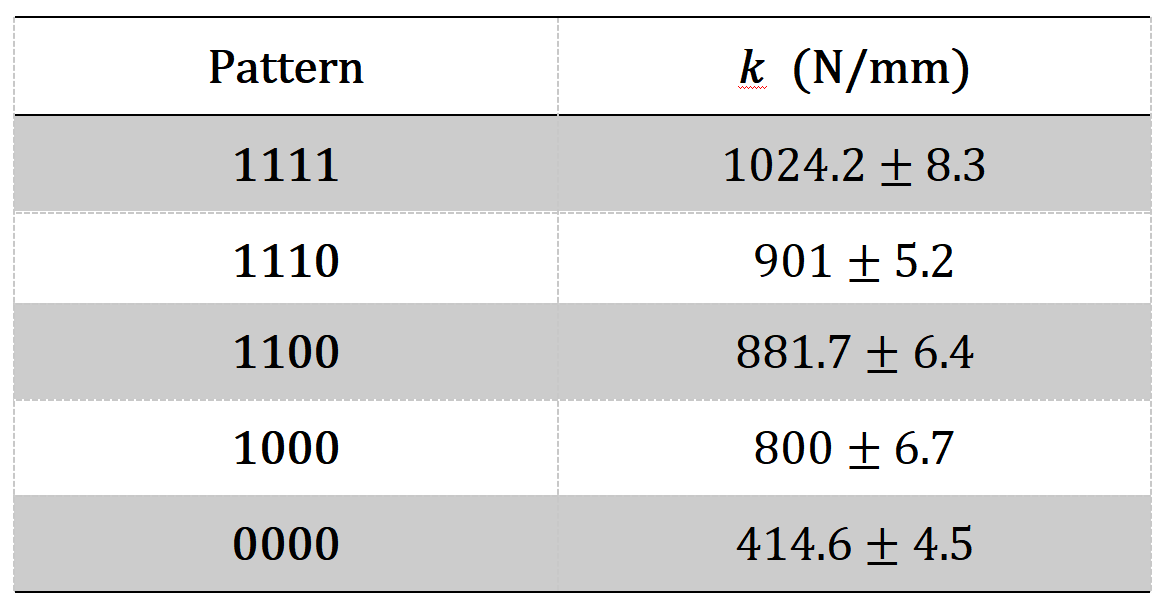
Table 4. Measured stiffness values k of the system comprising five units with binarized patterns achieved with overlap distances s = 10 (‘1’) and 0 mm (‘0’).
Implementation of Basic Logic Gates
Inter-unit interactions were used to form fundamental logic gates. The researchers reduced the number of vertical panels and first embedded two units in a system to create an electrical circuit. Copper foil was used to conduct current, with the vertical panels fully wrapped in copper foil. The buffer and NOT gate were established first:
Buffer: At rest, a small gap kept the circuit open. Compression brought the panels into contact, closed the circuit, and turned the LED on.
NOT gate: At rest, the panels were in contact and the circuit was closed. Compression separated the panels, opened the circuit, and turned the LED off.
After establishing the buffer and NOT gate, the team implemented the other six fundamental logic gates: AND, OR, XOR, NAND, NOR, and XNOR. Together, these gates can form a logically complete computing system capable of implementing Boolean functions with two input variables.
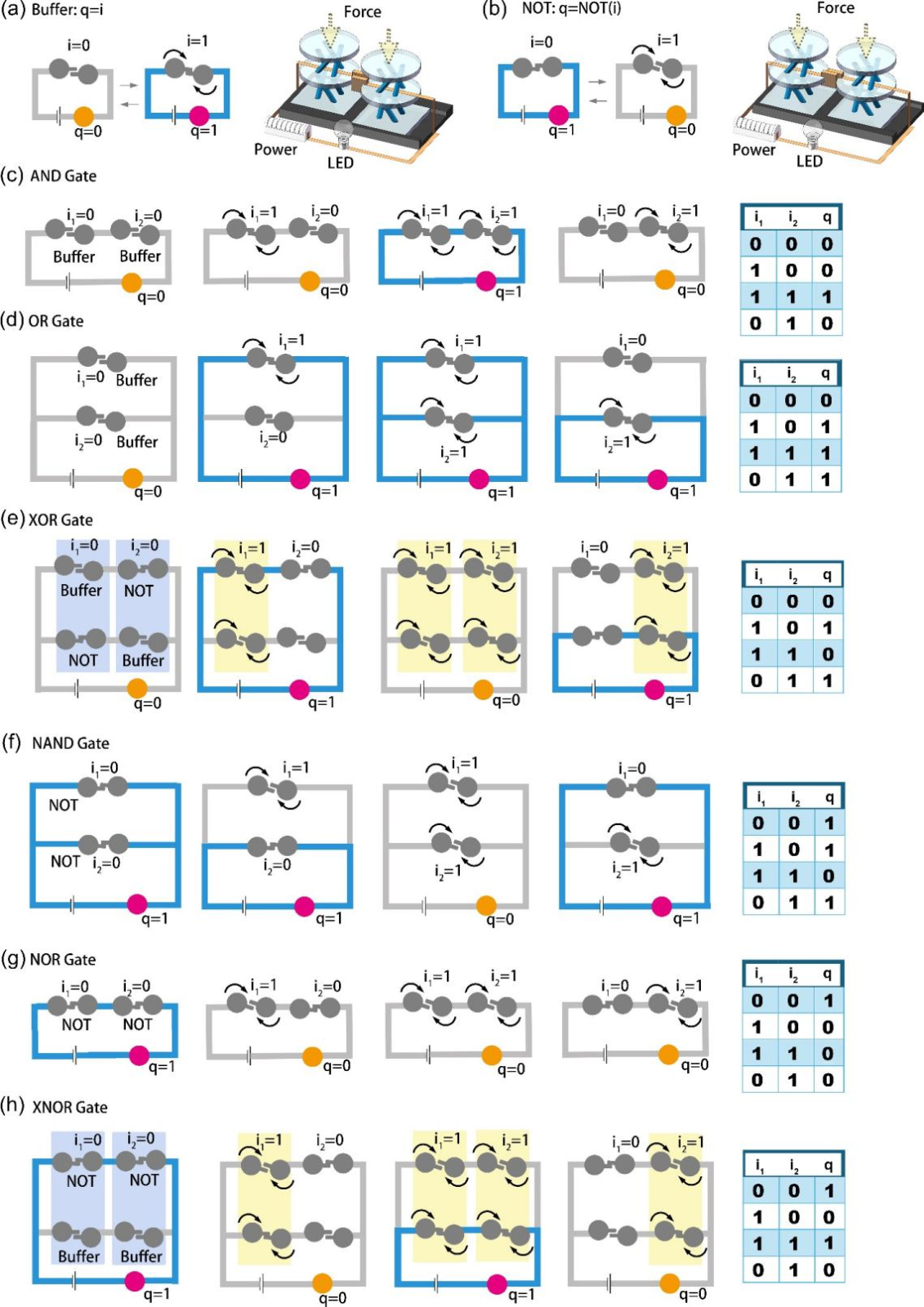
Figure 4. Creation of basic logic gates by combining the proposed units. Operational diagrams (the closed electric circuits transmitting current are marked in blue) and system overview of (a) the buffer and (b) the NOT gate representing the fundamental elements to build the following gates: (c) AND, (d) OR, (e) XOR, (f) NAND, (g) NOR and (h) XNOR shown together with their operational diagrams and truth table. For each system, four inputs (i1, i2) = (0, 0), (i1, i2) = (0, 1), (i1, i2) = (1, 1) and (i1, i2) = (1, 0), are performed for continuous operation, and the corresponding outputs q (LED light states) result correctly because they conform to the corresponding truth tables.
Implementation of Combinational Logic
Combinational logic extended the approach to more complex computing rules. A half-adder was implemented by integrating the fundamental gates. It consisted of an AND gate and an XOR gate, for a total of six logic gates and 12 chiral units. The experimental tests shown in the lower part of Figure 5c confirmed that the device produced the expected outputs. The demonstration showed that complex logic rules can be implemented in a mechanical system, as they are in electronic computing counterparts.
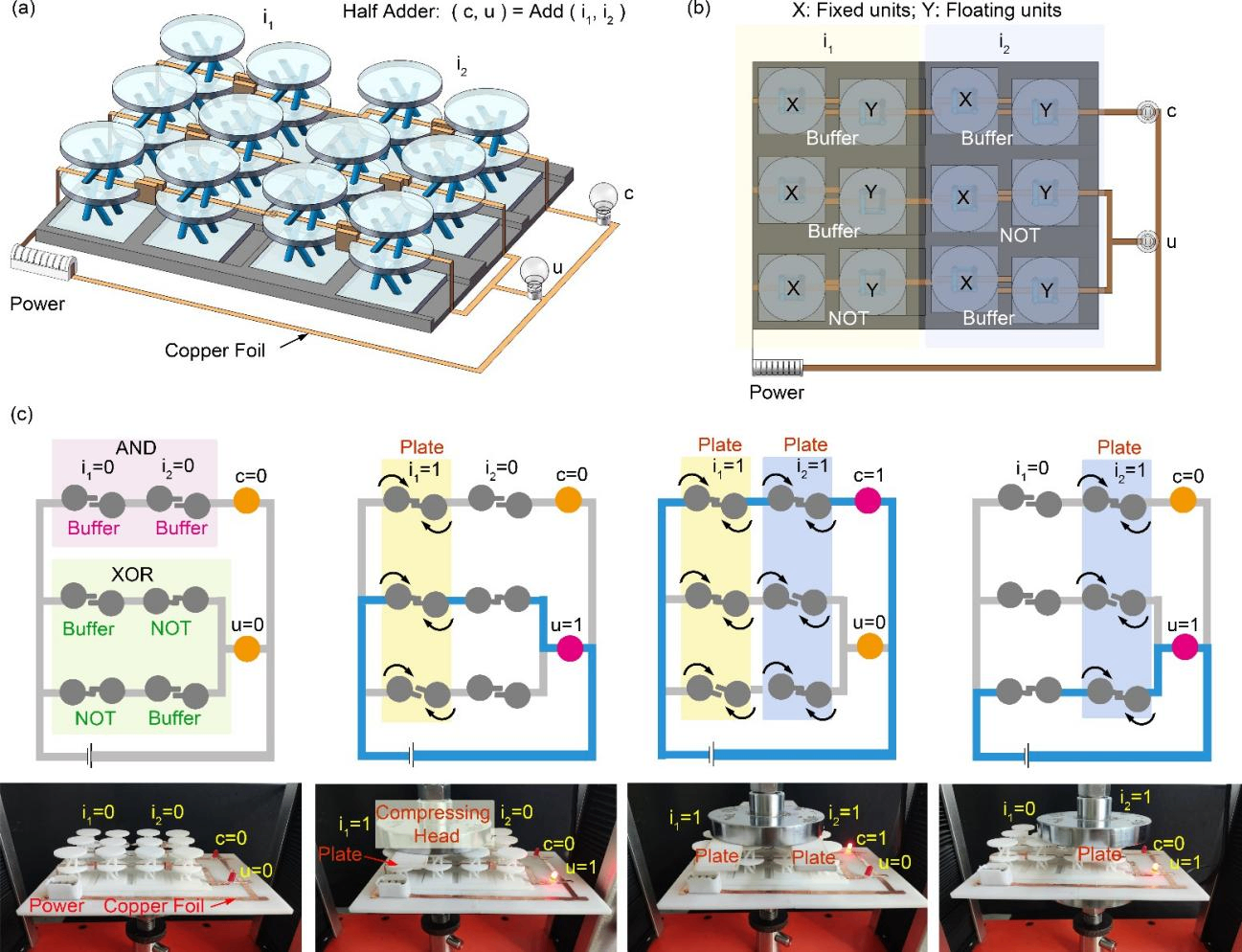
Figure 5. Design and implementation of a half-adder to achieve combinational logic functions using chiral structures with dm = 20 mm. Virtual model of the half-adder: (a) overview and (b) top view, with six pairs of units, two LED lights, copper foils, a substrate, anda power supply. (c) Logic diagrams (the active electric connections are marked in blue and yellow) corresponding to the photographs of the experiments while performing each configuration depending on the two inputs i1 and i2, and the resulting outputs c and u used to achieve the rule i1 + i2 = (c, u).
Role of NOKOV Motion Capture System in This Study
To quantitatively analyze the rotational deformation of the chiral structures during compression, the research team used NOKOV motion capture system to track two reflective markers fixed to the vertical panels and calculate changes in the twist angle. The resulting high-precision position data were assessed together with compressive force and displacement data to analyze the compression-twist response under different structural parameters and to support stiffness validation.
The motion capture system therefore provided the structural deformation measurement needed for chiral structure testing and mechanical property characterization. Stiffness itself was calculated from the force-displacement curves recorded by the universal testing machine; the optical data complemented this measurement by quantifying the associated rotation.
Frequently Asked Questions
Q1. What did the study primarily demonstrate?
The study proposed a method for implementing mechanical logic with 3D-printed chiral structures. Interactions among multiple chiral units created continuously tuneable stiffness and enabled mechanical logic gates and a combinational logic system in the form of a half-adder.
Q2. What role did NOKOV motion capture system play in the experiment?
NOKOV motioncapture system tracked reflective markers fixed to the vertical panels of the chiral structures. It measured changes in the twist angle during compression and supplied high-precision position data for analyzing structural mechanical behavior and supporting stiffness validation.
Q3. Which key parameters were measured?
The experiments recorded the twist angle, compressive force, and displacement of the chiral structures. Structural stiffness was calculated by fitting the elastic region of the force-displacement curves.
Q4. Why was twist-angle measurement necessary?
The twist angle quantitatively characterized the rotational deformation generated during compression. Together with the mechanical test results, it was used to evaluate how structural parameters influenced compression-twist coupling and stiffness.
Q5. What type of research application does this case demonstrate?
The study demonstrates the use of optical motion capture in chiral structure testing, structural deformation measurement, and the experimental validation of mechanical metamaterials. Similar research-grade motion capture systems can support advanced materials and robotics research when non-contact multi-point motion measurement is required.
Corresponding Author
Nan Yang, professor in the Department of Mechanical Engineering at the College of Engineering, Shantou University. His research interests include mechanical metamaterials, porous structural materials, artificial muscles, biomaterials, and structure-function relationships in materials.



 Room820, China Minmetals Tower, Chaoyang Dist., Beijing
 info@nokov.cn
 + 86-10-64922321